
Three phase induction motor is the type of electrical machine that uses three phase AC supply to convert electrical energy into mechanical energy . Three phase induction motor is a type of AC motor that works on the principle of electromagnetic induction . In this article I have explained about construction and working principle of three phase induction motor
Construction of three phase induction motor
it consists with different important parts
Stator

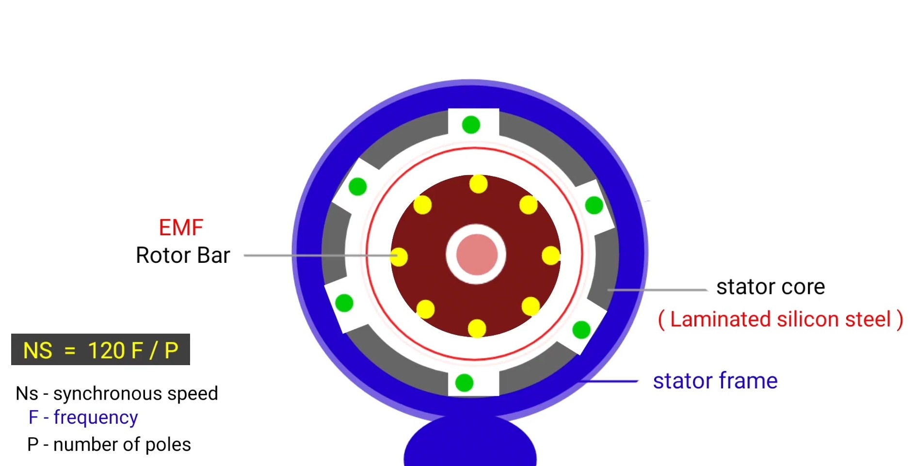
Stator is the stationery part of three phase induction motor. At the outer portion of motor frame is provided , frame is the outer body of the machine that is used to support the core and protect the inner parts of the machine . In case of a small size machine cast iron is used and in big size machine fabricated frame is used that reduces the heat .
Core :
stator core is made up of high graded Silicon Steel that supported by the outer frame . Main purpose of machine core is to carry the magnetic flux . We use Silicon Steel due to two important reason it provides high permeability and lower electance path for the magnetic field line so hysteresis loss reduces.
And lamination is used in the core , lamination is the arrangement of various thin sheets or strips that arranged together to consist the core we provide lamination to reduce eddy current loss. Each stamping of lamination remain insulated from each other by coating of varnish and thickness of lamination is about 0.3 to 0.5 mm.
slots are present at the inner portion of stator core where three phase winding is placed at the angle of 120° electrical . stator winding is also known as field winding
Stator winding : stator winding is also known as field winding that placed at inner slots of stator core . Winding is made up of copper due to their good electrical conductivity and three phase stator winding connected in either star or delta Connection .
Rotor
we can use two type of rotar in three phase induction motor
Squirrel cage rotor
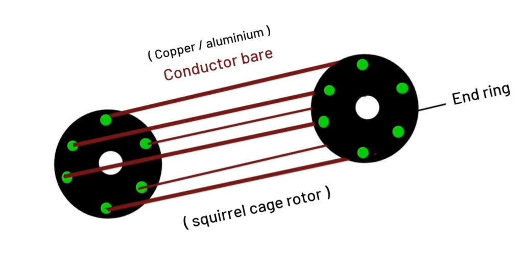
squirrel cage rotor consist with cylindrical laminated core. Rotor bar connected to heavy end ring . End ring made up of aluminium or copper by which skewed bars remain connected that made up of copper or aluminium . Copper bars connected with end ring like it completes the circuit . We design skewed bars to get uniform torque speed curve at different position.
Slip ring rotor :
slip ring rotor is also known as phase wound type rotor . It consist with laminated cylindrical core. At the outer periphery of slip ring rotor semi closed slots are present where 3 phase winding is placed. This is most commonly used rotor in 3 phase induction motor .

rotor winding connected in star connection and insulated by varnish. Slip ring mounted on rotor shaft with carbon brushes. And brushes are connected with variable resistance external variable resistance connected with rotor circuit with the help of carbon brushes.
Working Principle of three phase induction motor
first we give three phase AC supply in three phase stator winding that placed at 120 degree angle so due to three phase AC supply rotating magnetic field produces in the air gap between stator and router. That rotating magnetic field cuts the rotor bars so EMF induces in the conductor from Faraday’s law of electromagnetic induction , since rotor bar complete the circuit with heavy end ring so when EMF induces in the rotor bar then current circulates in the rotor conductor.
And due to current flow in the rotor conductor another magnetic field produces so due to interaction between rotating magnetic field and rotor field tangentially torque acts on the rotor and rotor starts to rotate. Because when current carrying conductor placed in magnetic field it experiences mechanical force on it , thus 3 phase induction motor operates.
NOTE :
3 phase induction motor is type of asynchronous motor so it rotates at less than synchronous speed ( Nr less than Ns ) . If speed of rotor Nr will equal to synchronous speed Ns then there will no relative motion between them and EMF will not induced in roto conductor.