split phase induction motor is the type of single phase induction motor that is used to convert electrical energy into mechanical energy. A split phase induction motor is also known as resistance start induction motor. In this motor, cage type rotor is used and two types of winding are used
main winding and starting winding placed on stator . Main winding is also known as running winding and starting winding is also known as auxiliary winding .
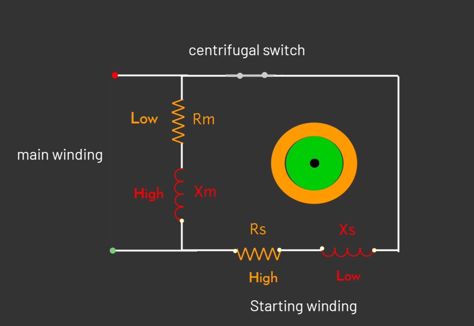
connection diagram of split phase induction motor
there are two types of windings are placed on the stator of split phase induction motor that is main winding and starting winding . Main winding has low resistance. And high inductive reactance. Whereas, in a starting winding resistance is high and inductive reactance remain low .
Also a centrifugal which is connected in the circuit when motor reaches their required speed, then starting winding disconnected through the centrifugal switch. Main winding and starting winding are displaced by 90° in a space.
working principle of split phase induction motor
since Main winding has low resistance and high inductive reactance while in starting winding high resistance and low inductive reactance . In this condition when single page AC supply. Flows in both winding.
Then phase difference created between main winding and starting winding. And due to phase difference between both winding rotating magnetic field produces in the air gap of a stator and rotor. Since phase difference between both winding is less than 90°. But the page difference is enough to rotate the rotor. And rotating magnetic field cuts the rotor bar.
Due to this another magnetic field produces around the rotor bars and due to the interaction between both magnetic field torque acts on the rotor , and rotor starts to rotate .
when rotor reaches the speed about 70 to 80% then starting winding, get disconnected by the help of centrifugal switch, and rotor rotates continuously with the help of main winding . in starting or during a starting the motor , if we change the terminal of the any one winding then motor will rotate in reverse direction.
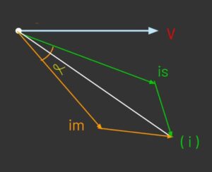
Phasor diagram of split phase motor
(v) is the reference voltage and current in starting winding (is) that lags by voltage at very small angle due to high resistance in a starting winding . Since main winding is highly inductive. So current in main winding (im) will lags by voltage. angle between (Im) and (is) is represented by (alpha) , due to this alpha angle rotating magnetic field, created between the air gap of rotor and stator .
And by phasor addition of current in main winding and current in starting winding, we get total value of current (i) . due to this total current flux produces in the air gap will be rotating in nature that is responsible to rotate the rotor .
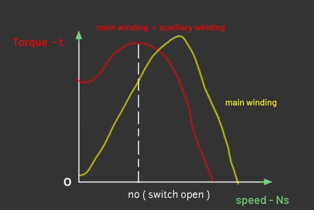
torque speed characteristics of split phase induction motor
Here n0 is the point at which centrifugal switch operates. A starting torque of the split phase induction motor is about 1.5 times of the full load torque . Red curve is showing when current is flowing in the main winding and starting winding. And at point n0 motor reaches the speed about 70 to 80% .
At that time starting widening, get disconnected by the help of centrifugal switch after that motor runs continuously with the help of main winding. So this is all about split phase motor.
important points
A split phase induction motor is type of single phase induction motor, just like other single phase motors it produces torque by splitting the current, phase difference created between main winding and starting winding.there are different type of single pairs, induction motors that we will cover in upcoming articles.