
DC generator is the electrical machine that is used to convert mechanical energy into dc electrical energy by the principle of electromagnetic induction. There are two types of generators, AC generator and DC generator. In this article, we will learn about DC generator.
construction of dc generator
DC generator consist with different main parts like other DC machines.
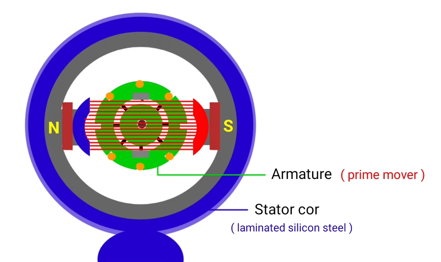
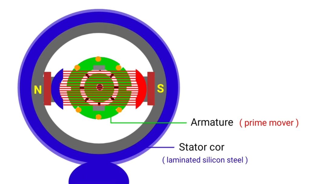
Stator : stationary part of DC generator is called stator
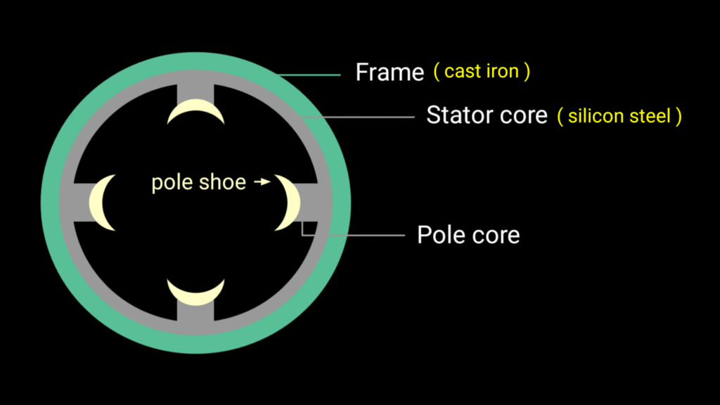
Stator frame : outer portion of machine is known as frame or yoke that play very important role in the working of dc generators. It provide mechanical strength and protect from mechanical damage. It provide the support to pole core and provide low reluctance path for the magnetic flux.
Stator core : stator core of DC machine is made up of laminated silicon Steel where poles are present at inner portion. Structure of poles like it consist with pole core and pole shoe. Silicon Steel has high permeability and it provide lower reluctance path for the magnetic field lines.
And lamination is the arrangement of various thin metal sheets where each sheet laminated to each other. We provide lamination in the machine core to reduce electrical losses like eddy current loss.
Pole core : sarface of pole core remain curved , usually Pole core and pole shoe are made up of cast steel and Pole core has different features.
- Pol core provide support to the field coil or exciting coil
- it spreads the magnetic flux towards rotor periphery of the DC machine.
- pole core increases the cross section area of magnetic path so reluctance of magnetic path decreases and magnetic field line easily passes.
Field winding : field winding placed around the pole core that is also known as exciting winding , main purpose of field winding is to produce magnetic flux. Field winding is made up of enameld copper wire, enamel coating provides insulation and we use copper wire due to their good electrical conductivity.
Field coils are connected in series and develop opposite magnetic polarity between adjacent pole.
Armature : the rotating part of DC generator is called as armature.

slots are present at the outer portion of armature core were we place armature winding. There are two main purpose of armature core armature core houses the armature conductor in the slots and it provides an easy path for the magnetic flux.
armature is the rotating part of DC generator so there will be more chance of hysterosis loss that’s why it is designed of laminated Silicon Steel. Diameter of lamination Stamping of armature core is about 0.3 to 0.5 mm and each laminations insulated to each other by the coating of varnish. And insulated armature coil is placed in the slots of armature.
energy conversion take place where armature winding placed. in case of DC generator mechanical power converted in electrical power. There are two types of armature winding Lap winding and wave winding
in lap winding conductor arranged like number of parallel path is equal to the number of pole. And in case of wave winding conductors are divided into two parallel path with irrespective to the number of pole of the machine.
Commutator : commutator is the most important part of the DC generator it rotates with armature and it is made up of hard drawn bars. Each commutator segment connected to the end of the armature coil. It connect the rotating armature with external circuit through brush and it convert the induced AC voltage in DC voltage.
Brush : Carbon brushes are attached with commutator segment that is used to collect the current from armature conductor.
Working principle of DC generator
first of all we give DC supply in field winding that is also known as exciting winding. So due to DC current flowing in the inductive winding, constant magnetic field produces. To produce filled flux permanent magnets are also used instead of electromagnet but in large DC generator generally we prefer electromagnet.
since DC generator convert mechanical Input in to electrical energy so we use external prime mover to give mechanical input. As prime mover we can use IC engine , steam engine , water wheel , turbines etc.

suppose we are using IC engine as prime mover to rotate the rotor and generator shaft is coupleed with IC engine shaft , when IC engine operates then coupled shaft of DC generator also rotate and receives the mechanical energy produced by IC engine.
when armature of DC generator rotates then armature conductor cuts the constant magnetic field that produced by field winding due to DC supply.

when armature conductor cuts the stationery magnetic field than EMF induces in the armature conductor from Faraday’s law of electromagnetic induction .
according to this principle whenever changing magnetic field cuts the stationery conductor or variable conductor cuts the stationery magnetic field then in both of the case due to relative motion between conductor and magnetic field EMF induces in the conductor.
in case of DC generator armature conductor is variable and field flux is stationery stationery so due to relative motion between stationary field flux and variable armature conductor EMF induces in the armature conductor. Armature conductors are sort circulated so AC nature of current generates in the armature conductor. Initially AC current induces in the armature winding whose direction is determined by the flaming right hand rule.
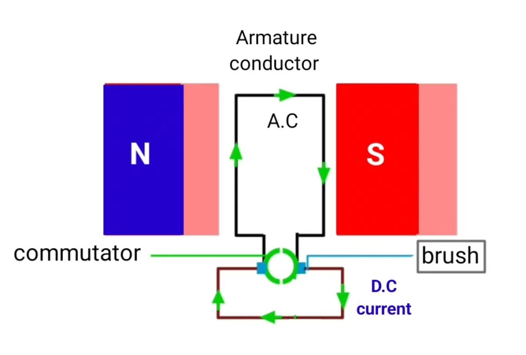
and commutator converts the induced AC current in armature winding to the DC current in output of DC generator. Commutator behave like mechanical rectifier that converts induced AC into DC current. Carbon brushes that attached with the commutator , collect DC current and supply to the load. Thus dc generator generates the dc current.
A DC Generator, or Direct Current Generator, is an electrical machine that converts mechanical energy into direct electrical energy. It works on the basic principle of electromagnetic induction, which was discovered by Michael Faraday. According to this principle, when a conductor moves in a magnetic field, an electromotive force (EMF) is induced in it. If the circuit is closed, current starts to flow through it. A DC generator follows this same rule but is designed in such a way that the output current always flows in one direction — hence the name “Direct Current Generator.” It is one of the most important machines used in the field of electrical engineering, power systems, and various industrial applications.
The main parts of a DC generator include the yoke, field poles, armature core, armature winding, commutator, and brushes. Each part has a special role in converting mechanical energy into electrical energy. The yoke forms the outer frame of the generator and provides mechanical support to the poles. It also acts as a protective cover for the internal parts and helps complete the magnetic path. The field poles are mounted on the yoke and are wound with field windings that carry current to create the magnetic field. These poles produce the necessary magnetic flux that cuts across the armature conductors to induce voltage. The armature core is a cylindrical structure made of laminated soft iron sheets to reduce eddy current losses. It carries the armature winding where the actual EMF is generated.
The armature winding is made up of copper conductors placed in slots on the armature core. As the armature rotates within the magnetic field, these conductors cut the magnetic lines of flux, and EMF is induced according to Faraday’s law. However, this induced EMF is alternating in nature because the direction of current changes with each half rotation of the coil. To convert this alternating current into direct current, a commutator is used. The commutator is a cylindrical structure made of copper segments insulated from each other. It acts as a mechanical rectifier, ensuring that the output current always flows in one direction. The brushes, usually made of carbon or graphite, press against the commutator surface and carry current from the rotating armature to the external circuit.
There are mainly three types of DC generators based on how the field winding is connected to the armature winding: separately excited, shunt-wound, and series-wound DC generators. In a separately excited DC generator, the field winding is powered by an external DC source, which means the field current can be controlled independently of the output voltage. This allows for precise control of the output, which is useful in laboratory and testing applications. In a shunt-wound DC generator, the field winding is connected in parallel (or shunt) with the armature. Because of this connection, the field current remains nearly constant, making the output voltage relatively stable. This type is widely used for battery charging and lighting purposes. The series-wound DC generator has its field winding connected in series with the armature winding, so the field current is the same as the load current. It provides a high voltage at light loads and a low voltage at heavy loads. Due to its poor voltage regulation, it is rarely used alone but can be combined with a shunt generator to form a compound generator. Compound generators combine the advantages of both shunt and series connections and are used where both good voltage regulation and high starting torque are required.
The working principle of a DC generator can be easily understood through Fleming’s Right-Hand Rule. According to this rule, if the thumb, forefinger, and middle finger of the right hand are held mutually perpendicular, then the forefinger indicates the direction of the magnetic field, the thumb indicates the direction of motion of the conductor, and the middle finger shows the direction of the induced current. When the armature rotates in the magnetic field, the conductors cut the magnetic flux, and EMF is induced in them. This induced EMF causes current to flow through the external circuit once the brushes and commutator complete the path.
The voltage equation of a DC generator is given by:
E = (P × Φ × N × Z) / (60 × A)
where,
E = Induced EMF in volts
P = Number of poles
Φ = Flux per pole in Weber
N = Speed of armature in RPM
Z = Total number of armature conductors
A = Number of parallel paths in the armature winding
This equation helps in designing and analyzing the performance of DC generators in various applications.
Losses in a DC generator include copper losses, iron losses, and mechanical losses. Copper losses occur due to the resistance of the winding. Iron losses, which include hysteresis and eddy current losses, happen in the armature core due to alternating magnetization. Mechanical losses are caused by friction and windage. The efficiency of a DC generator depends on minimizing these losses. Proper maintenance, lubrication, and use of high-quality materials can significantly improve its performance.
Applications of DC generators are quite vast, especially in areas where stable and controllable DC power is required. They are used in battery charging, electroplating, welding, DC motor drives, laboratories, and small power supply units. In earlier times, they were widely used in power stations before AC systems became dominant. Even today, DC generators are used in hybrid systems and renewable energy setups, such as wind turbines and small hydro plants, where DC output can be easily stored in batteries or converted to AC through inverters.
One of the major advantages of a DC generator is that it provides direct current without the need for external rectification. The voltage output can be easily controlled by adjusting the field excitation, which makes it suitable for precise control applications. However, DC generators also have some limitations such as higher maintenance due to brushes and commutator wear, lower efficiency at high power levels, and higher cost compared to AC alternators. Because of these factors, DC generators have largely been replaced by AC alternators in large-scale power generation. Still, they remain important for understanding the fundamentals of electrical machines and are used in specific industrial operations.
In conclusion, the DC Generator is a brilliant example of how the principles of electromagnetism are applied in real-world engineering. Even though modern power systems rely mainly on AC, the DC generator still holds great educational and practical value. It teaches the basic concept of energy conversion, magnetic flux, and induced EMF — concepts that are the foundation of all electrical machines. Whether used for teaching, testing, or powering specialized equipment, DC generators continue to demonstrate the beauty of electrical engineering in its simplest yet most powerful form.
Applications of dc generator
- there are different application of DC generator like it is used in function parties to produce electrical energy.
- it is used in hospitals.
- DC generator used in remote area.