
CRO – stands for cathode ray oscilloscope that is type of device or instrument which display the input electrical signal (current , voltage , power .. etc) in the form of graph. The CRO is used to analyse waveforms.
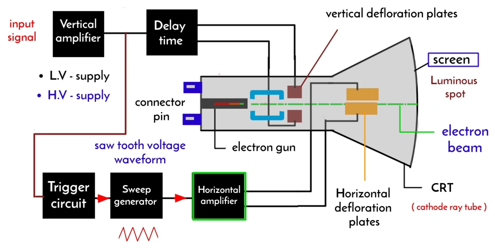
Construction of cathode ray oscilloscope (CRO)
cathode ray oscilloscope consist with different main parts that I have explain below.
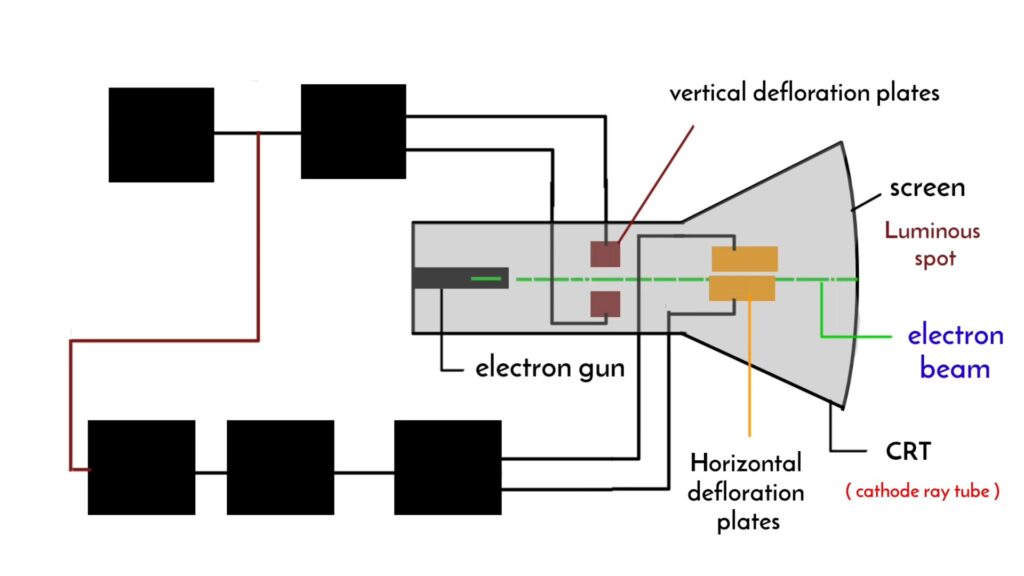
CRT : cathode ray tube display the measured electrical quantity in the form of graph, CRT consist with different element that improve its performance.
Electron gun : electron gun generates the electrons and generated electrons are strike on the screen as electron beam, Phosphorus crystal coating placed on the screen.
vertical deflection plate & horizontal deflection plate : both plates play very important role. When electron gun generate the electron beam that strikes on the screen, horizontal and vertical deflection plates prevents the electron beam from deflection. Electron beam travel in straight direction due to these plates.
screen on which electron beam Strike that remain curve that is known as Luminous spot.
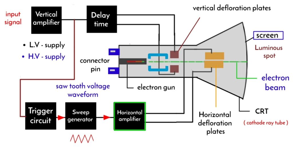
Vertical amplifier : vertical amplifier amplify the input signals and converts in required form like if we supply 10 volt and we have requirement of 12 volt then vertical amplifier will increase the input voltage from 10 volt to 12 volt.
Delay time : delay time prevent the vertical signal to flow in vertical deflection plate deflection plate, this particular block apply delay for the vertical signal. It delay the vertical signal because first of all horizontal circuit should operate.
Trigger Circuit : this circuit generate Trigger pulse for starting the time base generator or sweep generator, Sweep generator will start when Trigger circuit Trigger the pulse.
Sweep generator : time based generator or sweep generator consist with Uni junction transistor that is used to generate saw tooth voltage waveform and it play important role in horizontal deflection of electron beam.
Horizontal amplifier : horizontal amplifier connected to the horizontal deflection plate. Horizontal amplifier amplify the saw tooth voltage waveform that enters in horizontal amplifier from sweep generator. And amplified saw tooth waveform apply on horizontal deflection plate.
CRO working principle
low voltage supply is used to provide required voltage to All circuit of oscilloscope. And high voltage supply is used to provide required operating voltage in CRT for acceleration as well as relatively low voltage for the heater of electron gun, through which electrons get emits from electron gun. That’s why high voltage and low voltage used in the circuit.
when required high voltage apply in connector pins then heating element get heated and emits the electrons.
Electrons emits in very high speed so to travel the emitting electrons in straight direction we use focusing system that protect the electrons from deflecting then emitted electrons passes from horizontal and vertical deflection plate and finally electron beam strikes on the curve screen where Phosphorus crystal coating is placed.
when electrons strike on the phosphorous coating curve display then input signal display on screen in the form of wave or graph and we measure the value of voltage by analysing the displayed graph. Thus cathode ray oscilloscope operates with the help of different main elements.
important points
the main element of cathode ray oscilloscope is cathode ray tube , cathode ray tube plays very important role to analyse the electrical voltage current resistance and different electrical quantities by analysing the wave form. Cathode ray tube consist with different men elements like electron gun assembly, deflection plate assembly, fluorescent screen, glass envelope, so basically cathode ray tube is the device which is used to convert electrical signal into visible signal on CRT screen in form of graph.
as we know it is an instrument used to obtain the visual display of electrical signal. These days. It is one of the essential instrument required in physics and electronics laboratory. A CRO can be used to measure the amplitude and frequency of signal voltage.
it can be also used to measure phase difference between two ac voltages. This is all about cathode ray oscilloscope.
A Cathode Ray Oscilloscope (CRO) is an important electronic instrument used to observe, measure, and analyze electrical signals. It helps engineers and students visualize how voltage changes with time, by displaying the waveform of the signal on a screen. In simple words, CRO works like an electronic eye that shows what is happening inside an electrical circuit in real-time. Instead of just reading numbers from a meter, a CRO allows you to actually see the shape, frequency, and amplitude of the signal, which makes it an essential tool in laboratories, industries, and research fields.
The working principle of a CRO is based on the movement of electrons inside a vacuum tube, known as the Cathode Ray Tube (CRT). Inside the CRT, electrons are emitted from a heated cathode and accelerated by high voltage towards the screen. This beam of electrons forms a visible spot when it strikes the fluorescent screen. By controlling the movement of this electron beam, we can make it trace different waveforms that represent the input electrical signal. The deflection plates inside the tube play a major role here — the vertical plates (Y-plates) control the up-and-down movement, while the horizontal plates (X-plates) control the left-to-right movement of the electron beam.
A CRO mainly consists of four important parts — the Cathode Ray Tube (CRT), the Vertical Amplifier, the Horizontal Amplifier and Time Base, and the Power Supply Section. The vertical amplifier increases the strength of the input signal before it goes to the deflection plates. The horizontal section produces a time-varying voltage, called the time base, which moves the beam horizontally at a constant speed. This combination allows the CRO to display how the voltage of the signal varies over time, creating the waveform on the screen.
One of the biggest advantages of a CRO is its ability to measure different properties of an electrical signal with great accuracy. Using the screen grid, we can measure the amplitude, frequency, and phase difference between two signals. It is widely used in testing electronic equipment, troubleshooting circuits, designing communication systems, and studying the behavior of alternating current (AC) signals. For example, in a lab experiment, students use CROs to check the waveform of an audio signal or to verify the output of an amplifier.
Modern versions of CROs are known as Digital Storage Oscilloscopes (DSO). These advanced instruments can store waveforms, display them digitally, and even perform mathematical analysis. However, the basic principle remains the same as the traditional CRO. Understanding how a CRO works builds a strong foundation for anyone studying electronics or electrical engineering.
In conclusion, the Cathode Ray Oscilloscope is not just an instrument — it is a window into the invisible world of electric signals. By converting voltage into visual patterns, it helps engineers, researchers, and students deeply understand the behavior of electrical systems in a clear and interactive way.