

Reluctance motor is the type of special machine that consist of rotor and stator like other motors. And it is used to convert electrical energy into mechanical energy. Reluctance motor has lagging power factor and its efficiency is about 55 to 75% . It’s construction is almost like single phase induction motor but its working is different.
Construction of reluctance motor
it consists with different main parts

Stator : stationery part of motor is known as stator. At the inner portion of stator core poles are present and winding are present around the pole that is made up of copper we use copper material for winding due to their good electrical conductivity. Winding place on stator pole is known as main winding.
Stator core : stator core is made up of laminated silicon Steel , lamination is the arrangement of various thin strips that join together to build the core of machine we provide lamination in machine core to reduce eddy current loss . And silicon Steel provides lower reluctance path for the magnetic field lines.
Frame : outer portion of stator is known as frame. It protects the internal assembly of motor from any type of damage, frame is made up of cast iron or cast steel .
Rotor : squirrel cage type rotor is used in reluctance motor. Copper or aluminium bar are connected in Rotor, generally rotor teeth of the motor are removed from for places .
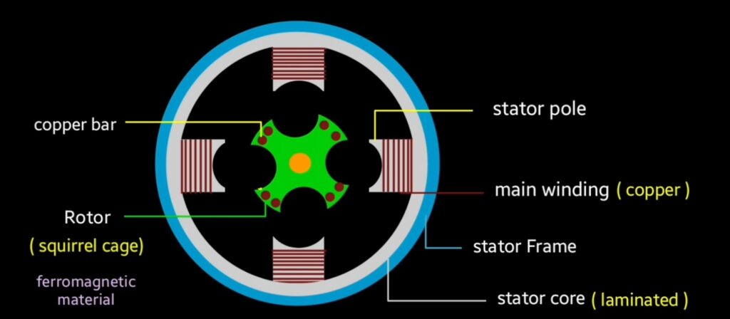
due to this action rotor behave like four pole rotor. Non uniform gap is present between stator and rotor. Rotor is made up of ferromagnetic material. This type of material has low reluctant and high permeability property.
Reluctance motor working principle
when reluctance motor connected to the single phase AC supply then current flows in main winding , as well as auxiliary winding also energize which is separate from main binding by some angle. Capacitor is connected in series with auxiliary winding that separates from meanwinding by the angle of theeta degree (Ø°) .
capacitor connected in auxiliary winding create the phase difference as a result rotating magnetic field (RMF) produces that rotates at synchronous speed. That is given by the equation of ( Ns = 120 F/P ) .
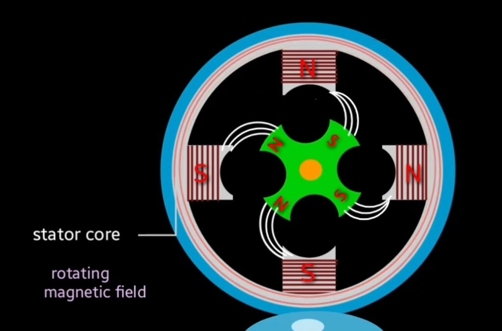
due to rotating magnetic field magnetic polarity also moves on stator pole. Since rotor is made up of ferro magnetic material which has property of high permeability and low reluctance.
due to permanent magnet, magnetic polarity will be constant on rotor pole. When ferromagnetic material placed in magnetic field then produced magnetic field lines completely passes through ferromagnetic material.

because reluctance of ferromagnetic material is lower than air and magnetic field lines always prefer to flow through low reluctance path. That’s why magnetic field lines passes through ferromagnetic material instead of air. Reluctance motor works on this concept.
magnetic field lines always try to flow through the ferromagnetic material instead of air so opposite polarity of stator and rotor attract to each other and starts to rotate. When motor speed reaches about 70 to 80% then auxiliary winding Remove from the circuit by the help of centrifugal switch.
After some time stator and rotor polarity get interlocked and rotor starts to rotate at synchronous speed with rotating magnetic field.

Thus reluctance motor operates and converts electrical energy into mechanical energy.
Characteristics

starting torque is depend on position of rotor. Value of starting torque varies. As we seen in the working when motor speed reaches 70 to 80% then auxiliary winding removed from the circuit by centrifugal switch and rotor continue rotates at synchronous speed with rotating magnetic field.
when motor load increases above the pull out torque then motor losses synchronism , but it will rotate continue as single phase induction motor up to its related torque. Reluctance torque experienced by ferromagnetic object that placed in external field. Reluctance torque is calculated by the formula ..
Trel = k ( v/f )² × sin (2Ç rel )
- Trel – average value of reluctance torque
- V – applied voltage
- F – line frequency
- ç rel – torque angle ( electrical degree )
- k – motor constant
This is all about reluctance motor