

Linear induction motor is the type of special motor which produces linear motion. It is used in industries for transporting the goods from one place to other place. In Linear induction motor, stator and rotor are called primary and secondary part . main feature of this motor it operates in linear direction that makes it special from other induction motor.
Linear induction motor categorised in two types
- Axial field motor – LIM
- transverse field motor – LIM
Construction
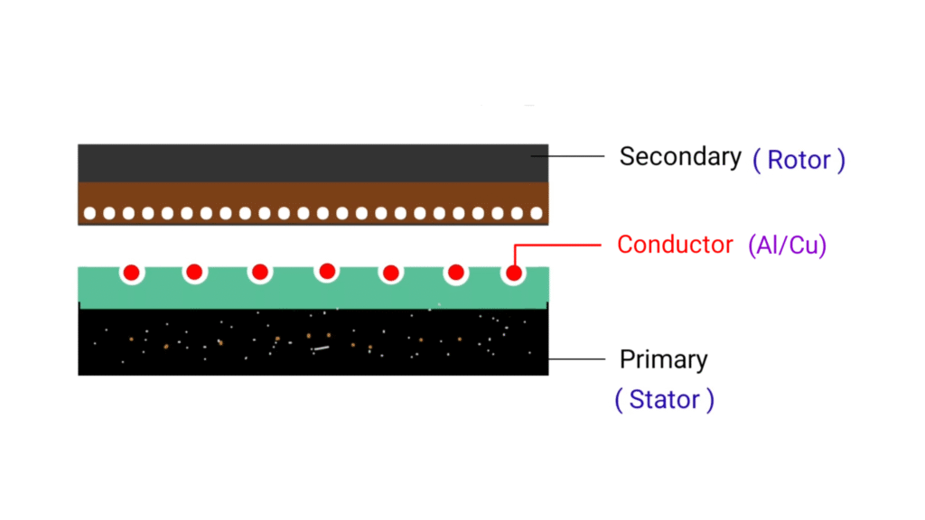
here basic construction diagram of Linear induction motor. You can just imagine we have three phase induction motor and we have cut the rotor and stator from the middle portion and we are spreading the motor or spread out it then that three phase induction motor will look like this basic construction diagram that I shown in the diagram above.
lower portion is the primary part that we consider as stator and upper portion is the rotor that we consider as the secondary part. Primary of the motor remain fixed just like stator of three phase induction motor and the secondary will move linearly, so you can say primary is the stator part and secondary is the rotor that will move in linear direction. Since 3 phase induction motor produces rotational motion while in Linear induction motor , rotor will travel in linear direction
Working principle of Linear induction motor
first we give three phase AC supply in the primary of the motor that we consider as stator. so due to three phase AC supply magnetic field will produces (Vs) m/s . Just like three phase induction motor here also winding is present in the form of conductor bars .
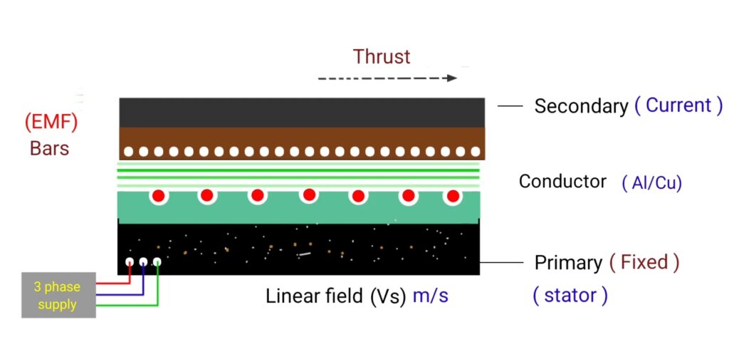
copper bars placed in the primary and secondary that short circuit with the end ring like bars of squirrel cage induction motor. So due to three phase AC supply , linear magnetic field produces whose nature is alternating due to AC supply that will link with conductor of secondary part. when changing magnetic flux links with copper bars of secondary part , then EMF producer in the copper bars of secondary part from faraday’s is law of electromagnetic induction .
since copper bars of secondary remain short circuit by end ring so due to EMF inducing in the secondary bars, current starts to circulate in the secondary copper bars. Where the direction of current remain outward . And as we know “when current carrying conductor placed in magnetic field then torque acts on the conductor .
So here also torque will develop on the copper bars of secondary but in case of Linear induction motor that torque will called as thrust and the direction of thrust will determine by the Fleming left hand rule. Fleming left hand rule gives the information about the direction of current magnetic flux and applied force . In case of Linear induction motor the direction of flux is downward , direction of current is outward and the direction of force is in the rightward direction . So the secondary of the motor will travel linearly in the rightward direction when thrust will apply. where speed is denoted by (v) and unit will be (V) m/s .
important points
Vs – linear travelling primary field (m/s)
Vs = 2tf1 m/s
- f1 – supply frequency (hz)
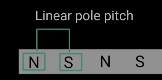
- t – linear pole pitch in metre
distance between two pole pitch is called as linear pole pitch.
V = speed of LIM = ( 1 – s ) Vs m/s
Slip (S) = Vs – V/Vs
Torque speed characteristics of Linear induction motor
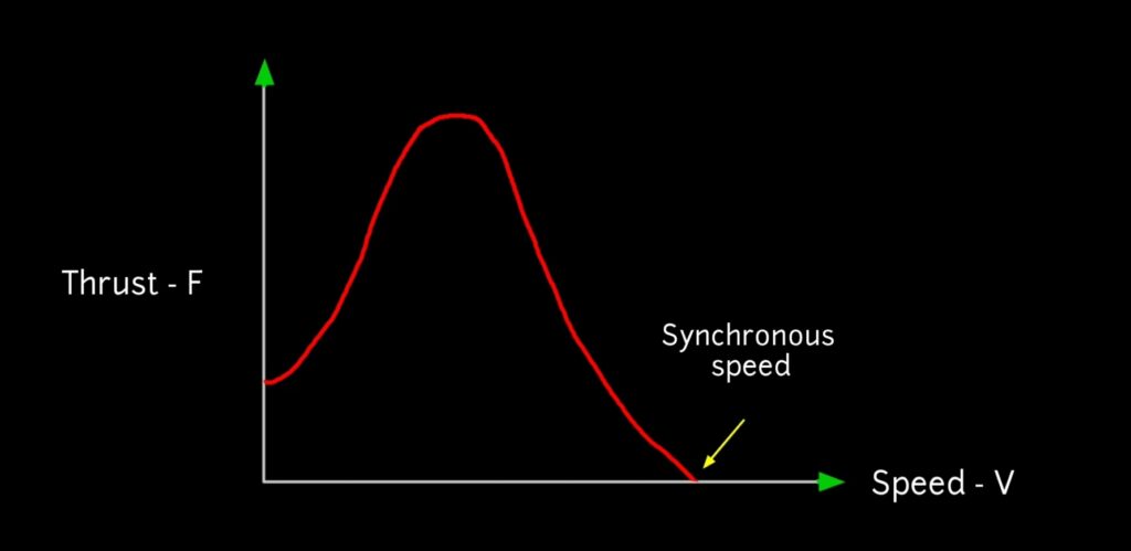
here it is torque speed characteristics of Linear induction motor between thrust (f) and speed (v) . If we compare the Rotary induction with linear induction motor, in Linear induction motor larger air gap is required hence the magnetising current is Greater and the power factor and efficiency is lower