

Slip ring induction motor is the type of asynchronous motor it does not rotates at synchronous speed . slip ring type rotor is used in this type of motor that is also known as wound type rotor . Slip ring induction motor is also known as wound rotor induction motor . Slip ring induction motor is used to convert electrical energy into mechanical energy.
construction of slip ring induction motor
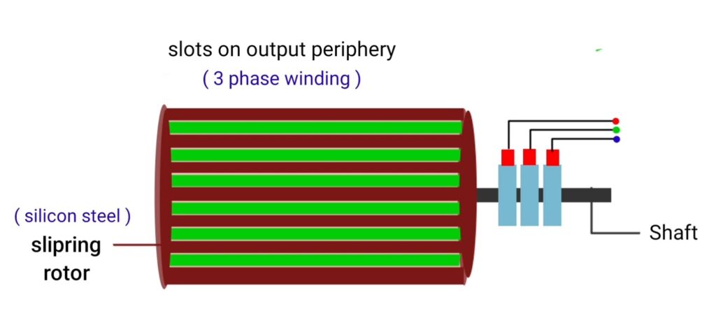
Slip ring induction motor has cylindrical rotor made up of laminated silicon steel . Silicon steel has high permeability property that provides slow reluctance path for the magnetic field lines. That’s why to design the core of rotor. We use silicon steel , semi closed slots are present at the Outer portion of the slip ring rotor where three phase winding is placed that is made up of copper or aluminium.
Generally, we use copper material due to their good electrical conductivity. In this type of motor rotor winding is connected in a star connection. And slip ring is mounted on the shaft of the motor with carbon brushes. Brushes are connected to the variable resistors that is also known as rheostat .
connection diagram
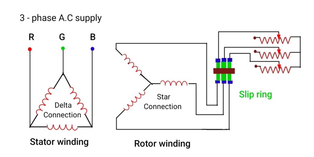
as you can see in the connection diagram, stator winding is connected in delta connection where we give three phase AC supply and rotor winding is connected in a star connection. Open end terminals of rotor connected with insulated slip ring and slip ring mounted on motor shaft with carbon brushes. Three variable resistor connected with the carbon brushes. That is also known as rheostat .
Slip ring is used in the circuit to connect external variable resistor with rotor winding. There are different benefits of connecting variable resistor in series with rotor winding. Starting current of motor get reduced , motor speed can be controlled using external resistor , we can vary or change the position of resistor. That’s why it is called as variable resistor .
Stator
Stator is the stationary part of slip ring induction motor, slots are present at the inner periphery of the stator where three phase winding is placed that is connected in Delta connection.
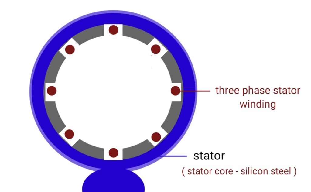
Stator core is made up of laminated silicon steel , lamination is the arrangement of various thin metal strip that arranged together, we provide lamination to reduce eddy current loss and silicon steel provides low reluctance path for the magnetic field lines because it has high permeability property.
Working principle of slip ring induction motor
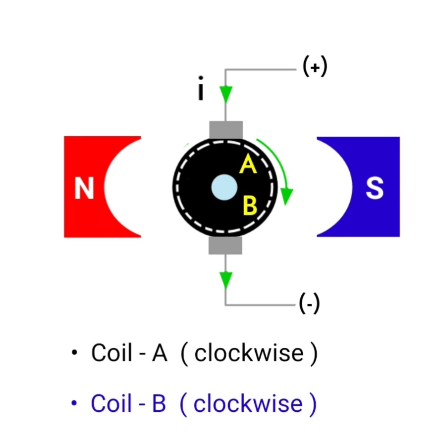
we give three phase A.C supply in the stator winding that connected in Delta connection at 120° angle . So due to 3 phase supply rotating magnetic field produces in the air gap of rotor and stator , rotating magnetic field rotates at synchronous speed that is given by ( Ns = 120 F/P ) , (Ns) is the synchronous speed , (F) is the frequency , (P) is the number of poles .
When rotating magnetic field cuts the rotor conductor then EMF induces in the rotor winding from Faraday’s law of electromagnetic induction , since rotor conductor, short-circuited, or provides the complete path so current circulates in the rotor conductor and produces another magnetic field . So due to interaction between rotating magnetic field and rotor magnetic field torque develops on the rotor and rotor starts to rotate where the speed of rotor is always less than synchronous speed that’s why this type of motor is also known as asynchronous motor .
Torque speed characteristics of slip ring induction motor
torque speed characteristics is the curve that plotted between torque and speed of induction motor .
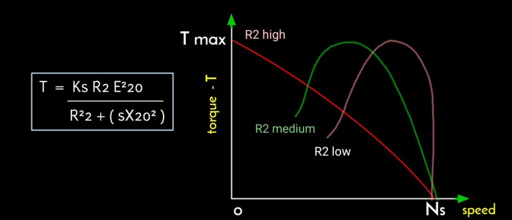
add the maximum torque speed of slip ring induction motor is expressed by, Nm = Ns ( 1 – Sm ) , Nm – maximum speed , Ns – synchronous speed , maximum torque remain independent on rotor resistance. And the greater value of (R2) The greater is the value of slip at which maximum torque occurs . And when rotor resistance increases then pull out speed of motor decreases and in this condition maximum torque remain constant .
Other topics
- Capacitor start capacitor run motor
- Split phase induction motor
- Capacitor start induction motor
- Shaded pole induction motor
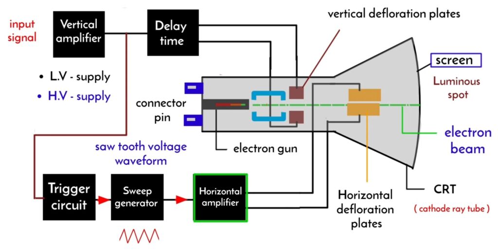
cathode ray oscilloscope working principle with diagram
CRO – stands for cathode ray oscilloscope that is type of device or instrument which…
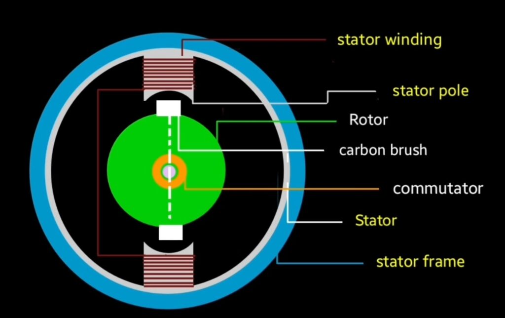
What is the working principle of a DC generator
DC generator is the electrical machine that is used to convert mechanical energy into dc…
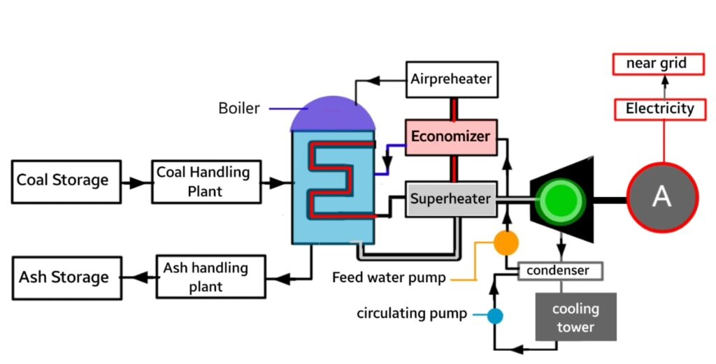
What is meant by thermal power plant
thermal power plant is a type of electricity generating station where heat energy converted into…
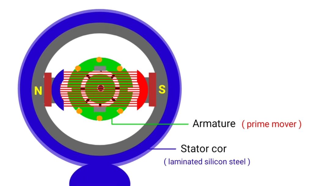
Repulsion motor principle
Repulsion motor is the special purpose machine that converts electrical energy into mechanical energy where…
Commutation in dc machine diagram
Commutation in DC machine is the process by which AC current induced in the armature…
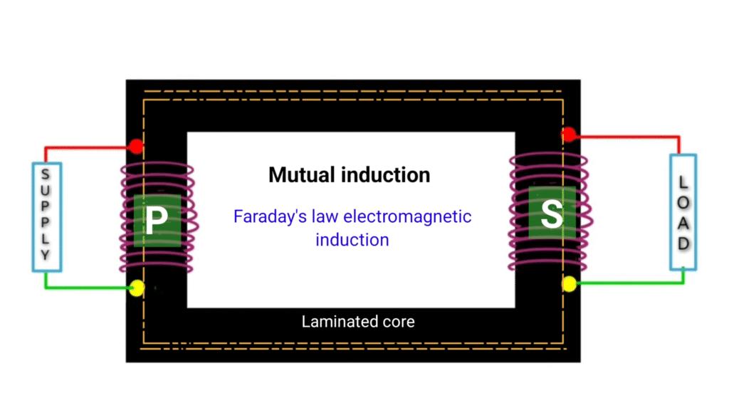
What is the working principle of single phase transformer
Single phase transformer is the static device or machine that is used to increase or…